
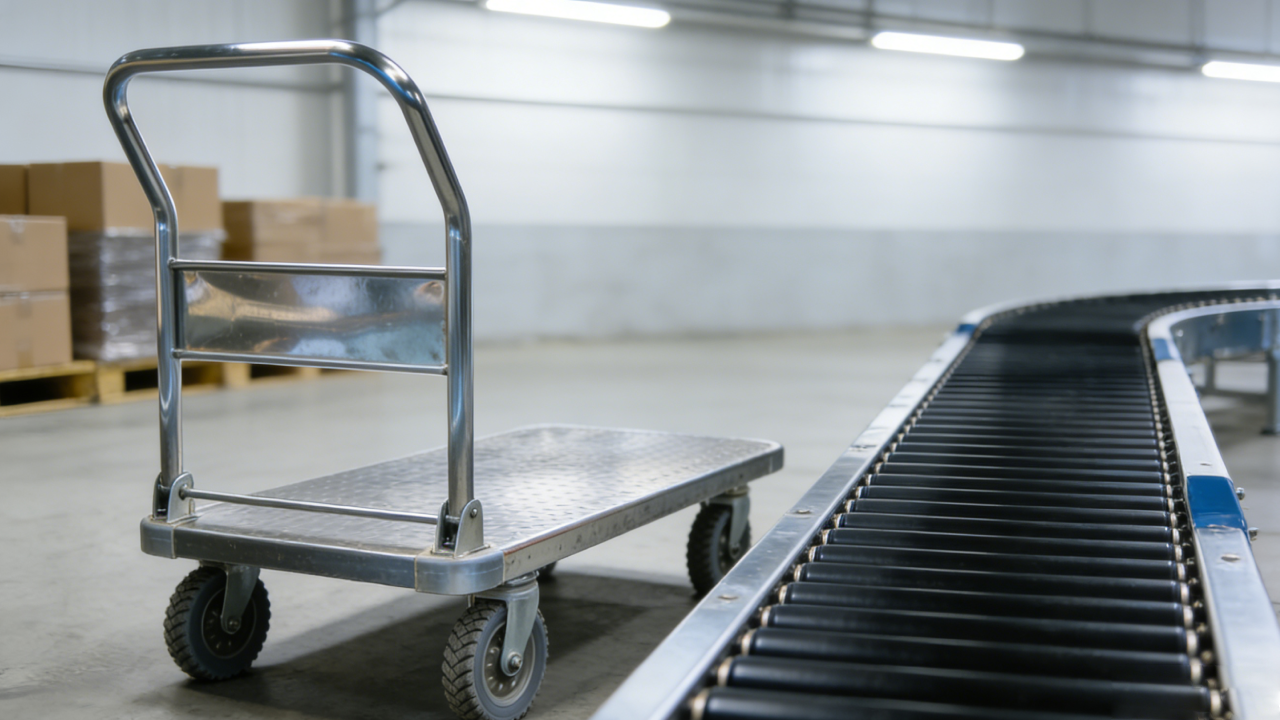
High‑torque brushless hub motors (BLDC / PMSM in-wheel designs) are increasingly adopted to upgrade industrial flatbed push carts used in warehouses, logistics yards and docks. This article explains the core electromechanical principles, compares brushless vs brushed options under variable loads, and provides actionable power‑to‑payload guidance (150W–500W) for common industrial scenarios.
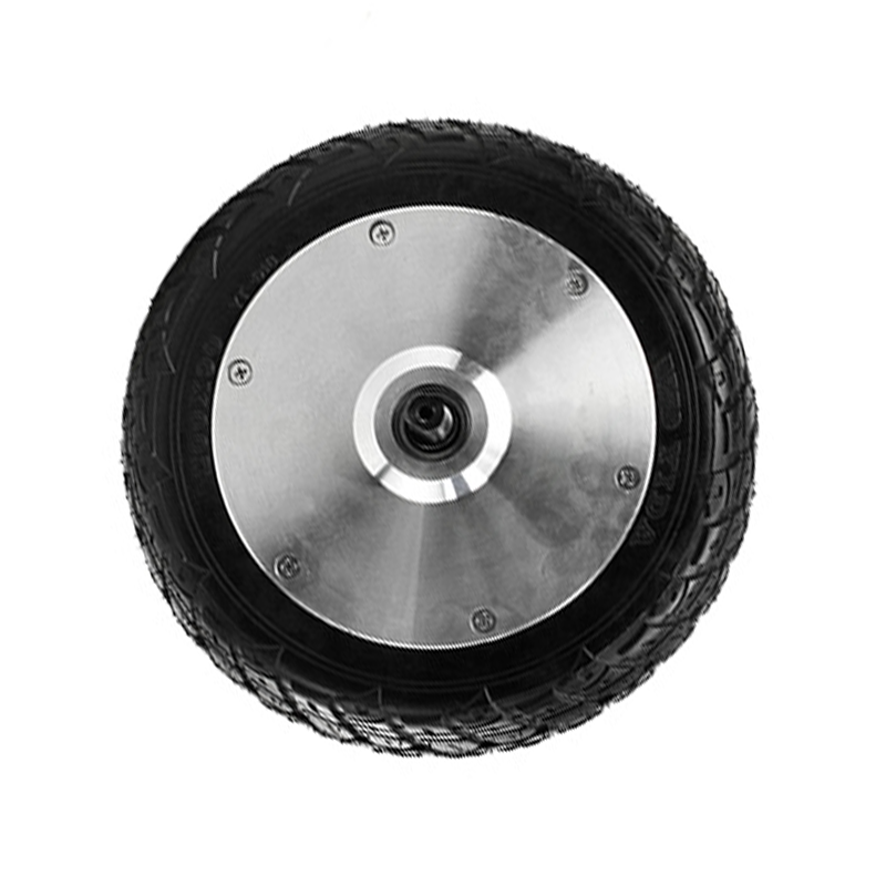
A brushless hub motor typically integrates a stator with multi‑phase concentrated or distributed windings and a rotor carrying high‑energy permanent magnets. When a three‑phase inverter drives controlled currents into the stator, a rotating magnetic field is produced; the rotor synchronizes to this field producing torque directly at the wheel. Modern motor controllers use field‑oriented control (FOC) to align current vectors with rotor flux, maximizing torque density and minimizing current draw under varying loads.
Compared to brushed motors, brushless hub motors offer measurable operational advantages in industrial handling:
Below is a practical mapping for direct‑drive hub motors when wheel rpm is kept low (approx. 200–350 rpm typical for industrial carts). Torque estimates use T(N·m) ≈ P(kW)×9550 / rpm as a guideline at nominal continuous speed.
| Motor Power (W) | Continuous Torque @ 300 rpm (N·m) | Recommended Payload (kg) | Typical Use |
|---|---|---|---|
| 150 W | ≈ 4.8 N·m | 50–120 kg | Light warehouse carts, small trolleys |
| 250 W | ≈ 8.0 N·m | 120–250 kg | Medium loads, mixed pick lines |
| 350 W | ≈ 11.1 N·m | 250–400 kg | Heavy floor carts, conveyor feed trucks |
| 500 W | ≈ 15.9 N·m | 350–500 kg | Dockside pulling, heavy material handling |

Brushed motors show faster torque decay and higher maintenance needs when loads fluctuate (brush wear, commutation losses). Brushless hub motors controlled by modern inverters maintain torque with closed‑loop current control and minimal commutation loss. Typical observable differences:
To maximize uptime and energy efficiency for industrial push carts, deploy the following control strategies:
Light, repetitive pick lines with smooth floors → 150–250 W hub motors. Mixed loads and frequent starts/stops → 250–350 W. Heavy dockside tugs with ramps → 350–500 W and controllers with robust thermal protection and hill‑hold.
Your scenario fits which configuration? Use the table above and the checklist to estimate required continuous torque and then select a motor-controller pair with at least 20–30% torque margin for peak events.
In field tests across warehouse fleets, retrofitting brushless hub motors and smart controllers reduced operator effort by up to 40% and energy consumption per shift by 15–25% (depending on duty cycle and regen implementation). Maintenance intervals lengthened due to eliminated brush replacement and lower commutation heat.
For engineers specifying systems, a conservative approach is to size for continuous duty at expected max gradient plus a 25% safety factor. Verify battery capacity and peak current capability—500W continuous at 48V typically requires ~10–12 A continuous and higher short‑term peaks for torque bursts.
Request a tailored motor + controller package and a load‑matching study for your carts.
Note: The provided torque and payload mappings are engineering guidelines for early specification and comparison. Detailed selection should include slope, wheel diameter, duty cycle, ambient temperature and electrical system constraints.
 43
|
43
|
 camping trailer power upgrade
brushless hub motor
hub motor installation tips
off-road hub motor performance
322
|
IP67 waterproof motor
electric go-kart motor sealing
hub motor dustproof solutions
outdoor e-vehicle motor maintenance
camping trailer power upgrade
brushless hub motor
hub motor installation tips
off-road hub motor performance
322
|
IP67 waterproof motor
electric go-kart motor sealing
hub motor dustproof solutions
outdoor e-vehicle motor maintenance


.png?x-oss-process=image/resize,h_100,m_lfit/format,webp)
.png?x-oss-process=image/resize,h_100,m_lfit/format,webp)
.png?x-oss-process=image/resize,h_100,m_lfit/format,webp)


